

 русский
Selecting an electrical cable winch is an engineering decision that directly affects cable lifespan, installation safety, and operational efficiency. Unlike a standard lifting winch, a cable winch must be precisely matched to the cable's diameter, weight, minimum bend radius, and the tension required during pulling or spooling. A mismatch can kink an expensive power cable, crush the conductors, or create a safety hazard during deployment. This electrical cable winch selection guide outlines the critical steps—from calculating drum capacity and line pull to specifying the drive type and control system—so that the selected winch integrates reliably into your cable handling operation, whether on a construction site, in a factory, or aboard a vessel.
Content
- 1 Define the Application and Cable Pulling Requirements First
- 2 Calculate Cable Drum Capacity for Your Specific Cable Length and Diameter
- 3 Evaluate Drive Type and Control System: Manual, Electric, or Automatic
- 4 Understand Low Voltage vs. High Voltage Cable Winch Design Differences
- 5 Assess Factors Affecting Cable Winch Performance and Service Life
- 6 Integrate the Winch into a Complete Cable Handling System
Define the Application and Cable Pulling Requirements First
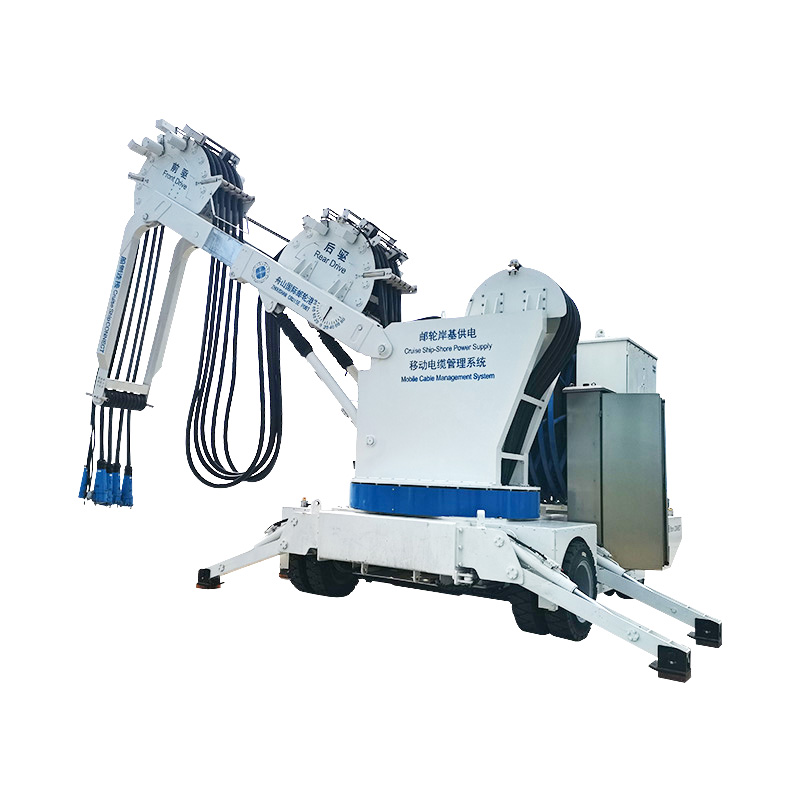
Winch selection starts with a clear definition of the task. The requirements for an electric cable pulling winch used to draw cable through underground ducts differ fundamentally from those of a shore power cable management system that must spool a heavy, flexible cable hundreds of times with minimal operator intervention. Begin by documenting the cable specifications: outer diameter, weight per meter, minimum bend radius, and the total length to be handled. The winch drum core diameter must be at least 15–20 times the cable's outer diameter to avoid exceeding the bend radius and damaging the insulation. For a cable with a 60 mm outer diameter, the drum core must be no smaller than 900–1,200 mm.
Next, determine the required line pull force. This is not simply the weight of the cable; it is the tension needed to overcome friction in the duct, pull the cable off a supply reel, or maintain back tension during laying. For duct pulling, the tension can be estimated using the cable weight, the coefficient of friction (typically 0.3–0.5 for lubricated ducts), and the route geometry including bends. For a straight pull of 200 meters of cable weighing 5 kg/m in a lubricated duct, the pull force may be around 3–5 kN, but bends and elevation changes multiply this value. A cable winch capacity calculation must also factor in a safety margin: the winch's rated line pull should exceed the calculated maximum tension by at least 25% to account for unforeseen resistance and to avoid operating the winch continuously at its maximum rating.
Calculate Cable Drum Capacity for Your Specific Cable Length and Diameter
Cable drum capacity selection is a geometric calculation that ensures the winch can store the entire cable length in orderly layers without exceeding the drum flange diameter. The capacity of a drum depends on the core diameter, the flange diameter, the drum width, and the cable diameter. A rough capacity in meters can be estimated using the formula:
L = (π × W × (Df² – Dc²)) / (4 × d²)
Where W is the drum width between flanges, Df is the flange diameter, Dc is the core diameter, and d is the cable diameter. This formula assumes perfect winding with no gaps. In practice, a level-winding mechanism improves packing density to about 85–95% of the theoretical maximum. When specifying the drum, also consider that the first layer of cable experiences the highest compressive stress, and the outer layers must not crush the inner layers. As a rule of thumb, the total cable diameter on the fully wound drum should not exceed 2.5 times the core diameter to limit this compressive effect.
| Application | Cable Diameter (mm) | Typical Drum Core (mm) | Typical Capacity (m) |
|---|---|---|---|
| Shore power cable for cruise ships | 60–100 | 1,200–2,000 | 50–150 |
| Subsea umbilical deployment | 40–80 | 800–1,500 | 200–1,000+ |
| Utility cable pulling (duct) | 20–50 | 400–800 | Capstan design, no storage drum required |
For pulling winches using a capstan rather than a storage drum, the capacity calculation shifts to the pulling rope length and capstan grip. The capstan's diameter is still based on the pulling rope's bend radius, and the groove profile must match the rope diameter to prevent slippage.
Evaluate Drive Type and Control System: Manual, Electric, or Automatic
The choice of drive and control determines how the winch integrates into your workflow. A basic cable pulling winch may use an electric motor with a simple pendant control for forward, reverse, and stop. This is adequate for occasional duct pulling where an operator is always present. For applications requiring precise tension control—such as laying fiber optic cables or subsea umbilicals—a variable frequency drive (VFD) with a PLC-based automatic cable reel system is the standard. A VFD allows the motor speed to be infinitely adjustable and can maintain constant tension by monitoring a load cell and adjusting the motor torque in real time.
Hydraulic drives remain popular in marine cable winch selection because they offer high torque at low speeds without the explosion-proofing concerns of large electric motors in certain hazardous areas of a vessel. However, electric drives are gaining ground with the advent of high-efficiency permanent magnet motors and the push toward all-electric ship designs. For a shore power cable management system on a cruise ship, an electric drive with a slip ring assembly is preferred because it can be integrated into the ship's power management system, and the slip ring allows the cable to remain connected to the shore supply while the winch pays out or takes in cable. When selecting the control system, consider whether the winch will be operated from a local pendant, a remote console, or as part of an integrated vessel automation system. The control architecture must match the skill level of the operators and the criticality of the cable handling operation.
Understand Low Voltage vs. High Voltage Cable Winch Design Differences
The low voltage vs high voltage cable winch distinction is not about the winch's own motor voltage but about the voltage rating of the cable being handled. Low-voltage cables (typically up to 1 kV) are lighter and more flexible, and winches for these cables can use smaller drum cores and simpler level-wind mechanisms. A winch handling a 0.6/1 kV power cable for a construction site might have a drum core of 400–600 mm and a line pull of 5–20 kN. As the cable voltage increases to 6.6 kV, 11 kV, or 33 kV, the cable becomes progressively thicker, heavier, and stiffer due to increased insulation thickness and semiconductive layers. A high-voltage cable requires a drum core of at least 20 times the cable diameter, a more robust level-winding system to control the stiffer cable, and often a tensioner to prevent the outer layers from crushing the inner layers on the drum.
For a cable winch for cruise ships handling 6.6 kV or 11 kV shore power cables, the winch must also incorporate a high-voltage slip ring that can transmit power and data signals while rotating. This slip ring is a precision component designed to maintain continuity without arcing, and it must be enclosed to prevent exposure to salt spray. The voltage rating of the slip ring must match the cable voltage, and the insulation resistance must be tested regularly. When selecting a winch for high-voltage cables, verify that the manufacturer has experience with the specific cable type and that the drum, slip ring, and control system are all rated for the nominal cable voltage plus a safety margin.
Assess Factors Affecting Cable Winch Performance and Service Life
Several factors affecting cable winch performance should be evaluated before purchase, as they directly impact reliability and the total cost of ownership over the winch's life. The operating environment is the first consideration. A winch installed on an open deck must be rated for marine conditions: the motor enclosure should be at least IP56, the structural steel must be coated with a marine-grade paint system, and all fasteners should be stainless steel. In a factory or warehouse, an IP44 motor enclosure with a standard industrial paint finish may be adequate. Temperature extremes affect both the motor's cooling capacity and the viscosity of gearbox oil; winches destined for arctic or desert environments may require synthetic lubricants, heating elements, or special motor insulation.
The duty cycle defines how long the winch can operate continuously without overheating. A winch rated for S3 40% duty cycle can run for four minutes out of every ten at rated load; exceeding this will cause the motor to trip on thermal overload or burn out. For cable winch for cruise ships that must spool and unspool shore power cables frequently during port calls, a higher duty cycle such as S4 or S6 with frequent starts and stops may be required. Gearbox efficiency and service life are other key parameters; a helical gearbox is more efficient and quieter than a worm gearbox, but worm drives are inherently self-locking and may be preferred for holding a load without a separate brake. The selected cable pulling winch specifications should include the gearbox type, ratio, and service factor—a service factor of 1.5 to 2.0 is typical for industrial winches to absorb shock loads without gear tooth failure. Finally, consider the availability of spare parts and service support; a winch from a manufacturer with a global network of technicians simplifies maintenance, especially for marine applications where the vessel may be in a different port each week.
Integrate the Winch into a Complete Cable Handling System
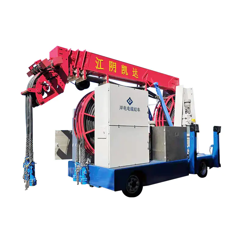
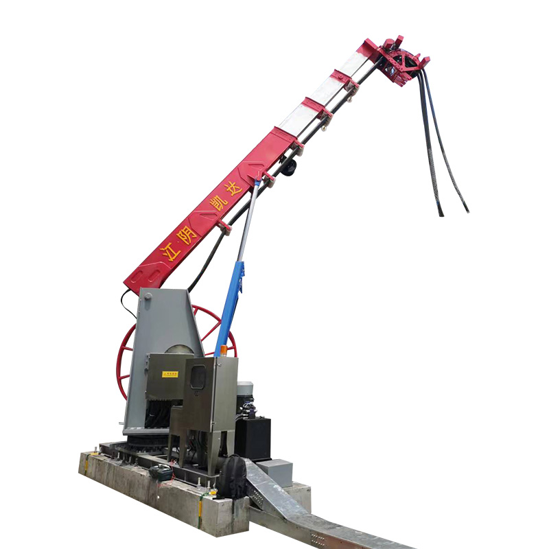
A winch rarely operates in isolation; it is one component of an industrial cable management system. When selecting a winch, consider how it will interface with the cable supply reel, any tensioners or counter-rollers, and the downstream cable routing. For a pulling application, the winch must be aligned with the duct mouth or cable tray to prevent chafing. A swivel base or a pivoting fairlead on the winch frame can accommodate some angular misalignment. For a storage winch, a dancer arm or tension feedback device is essential to maintain consistent lay tension and prevent slack layers that can snag during payout. In a shore power cable management system, the winch is often installed on a traversing platform that moves the drum laterally to follow the ship's movement during tide changes, preventing side loading of the cable at the fairlead. Investing in a properly integrated system, with each component sized and aligned correctly, maximizes the service life of both the cable and the winch, turning a high-value capital asset into a reliable, low-maintenance part of your operation.