

 русский
Before you order a crew to pull 200 metres of low-voltage cable through three conduit bends, run one number: the pulling tension. A cable pulling tension calculator estimates the force needed to drag the cable into place, and that estimate tells you whether the job can be done safely by hand or should be handled by a cable pulling winch. The math is not a formality; it is the first step in preventing cable damage, lost labour, and rework.
This guide explains what these calculators do, which inputs really matter, how to interpret the result, and the mistakes that make a safe-looking number unreliable.
Content
- 1 What a Cable Pulling Tension Calculator Actually Calculates
- 2 Critical Inputs: Friction Coefficient and Cable Weight
- 3 Interpreting the Output: Compare Against the Cable's Limits
- 4 Common Mistakes That Make the Calculator Result Meaningless
- 5 Straight-Pull Screening vs Full Route Analysis
- 6 A Practical Example: 150 m Pull with One 90° Bend
- 7 When the Calculated Tension Exceeds Practical Limits
- 8 One-Time Pulling vs Continuous Reeling
- 9 Calculator Limitations and When to Bring in an Engineer
What a Cable Pulling Tension Calculator Actually Calculates
For a straight, horizontal section, the basic screening formula is:
T = μ × W × L
where T is the tension at the pulling end, μ is the friction coefficient between cable and conduit, W is the weight of the cable per unit length, and L is the length of the section. If the route has a bend, the tension on the far side of the bend is approximately:
T_out = T_in × e^(μθ)
where θ is the bend angle in radians. Most practical calculators use this exponential relationship for each bend and add the results along the route. They also calculate sidewall pressure, which is the radial force per unit length at a bend, usually T divided by the bend radius R.
| Variable | Meaning | Typical unit |
|---|---|---|
| μ | Friction coefficient | Dimensionless |
| W | Cable weight per unit length | N/m or lbf/ft |
| L | Pull length | m or ft |
| T | Tension at pulling point | N or lbf |
| R | Bend radius of conduit or tray | m or ft |
Critical Inputs: Friction Coefficient and Cable Weight
The output is only as good as the friction coefficient you enter. A change from 0.20 to 0.40 doubles the straight-line tension. Typical values for conductor pulling inside conduit are:
- Steel conduit, no lubricant: 0.35–0.50
- PVC conduit, no lubricant: 0.30–0.45
- Concrete duct, no lubricant: 0.50–0.70
- Any conduit with an approved pulling lubricant: 0.15–0.25
Always treat the friction coefficient as an estimate, not a measured constant. Surface condition, conduit length between access points, cable jacket material, and lubrication application all change it. Cable weight is easier: get it from the manufacturer's data sheet or weigh a sample. Do not use the weight of the whole reel.
Interpreting the Output: Compare Against the Cable's Limits
The calculated tension is not a target; it is a demand. The demand must be lower than the cable's maximum allowable pulling tension and sidewall pressure. For copper conductors, one common screening guidance is 0.008 pounds-force per circular mil of conductor cross-section. A 500 kcmil copper conductor therefore allows about 4,000 pounds-force of tension before further check. For aluminium, use approximately 0.006 pounds-force per circular mil.
Sidewall pressure is the second limit. A common screening cap is 300 lb/ft (4.4 kN/m) for low-voltage cables, while some larger single-conductor cable designs allow 500 lb/ft (7.3 kN/m). Confirm both values in the cable manufacturer's installation manual. If the calculator result is close to either limit, refine the inputs or change the route before pulling.
Common Mistakes That Make the Calculator Result Meaningless
The most common reason a cable pulling tension calculator gives a misleading number is not bad software; it is bad input logic. Watch for these:
- Using one friction coefficient for the entire route even though lubricated sections and dry sections behave differently.
- Ignoring bends. A straight-pull model cannot see the extra tension created by each 45° or 90° turn.
- Forgetting that the cable pays off from a reel. Tension at the reel adds to the tension in the conduit, especially if the reel is not guided properly.
- Entering total cable length rather than the length of each conduit section.
- Running the calculation without a safety factor for unexpected rough spots, crush points, or conduit debris.
A calculator is a screening tool. It tells you whether a pull is worth studying in detail; it does not approve the pull.
Straight-Pull Screening vs Full Route Analysis
Many free cable pulling tension calculators use a fixed screening model: straight conduit, constant friction, and no cumulative bend analysis. That is fine for a first check, but not for a route with bends. If your route has bends, apply the exponential factor for each bend in sequence. Even a single 90° bend at the end of a straight section adds a significant percentage.
| Bend angle | θ (radians) | Multiplier e^(0.2θ) |
|---|---|---|
| 30° | 0.524 | 1.11 |
| 45° | 0.785 | 1.17 |
| 60° | 1.047 | 1.23 |
| 90° | 1.571 | 1.37 |
With two 90° bends in one pull, the multiplier compounds to roughly 1.37 × 1.37 = 1.87. Tension that looked reasonable in a straight-pull model can exceed the cable limit once bends are included.
A Practical Example: 150 m Pull with One 90° Bend
Suppose you are pulling a cable with a mass of 0.35 kg/m, which corresponds to a weight of 3.43 N/m, through a lubricated PVC conduit with a friction coefficient of 0.20. For a 150 m straight section, the tension at the pulling end is:
T1 = 0.20 × 3.43 N/m × 150 m = 103 N
If a 90° bend sits at the end of that section, multiply by 1.37:
T2 = 103 N × 1.37 = 141 N
Add a 10% safety margin and the target pull force is about 155 N (35 lbf). That is easily within manual capability.
Now change the cable to a heavier 500 kcmil copper conductor weighing about 2.2 kg/m, use the same 150 m distance and one bend, and the tension becomes 0.20 × 2.2 × 9.81 × 150 × 1.37 = 887 N (199 lbf). Double the length and add a second bend, and you are above 2,000 N. At that point you are no longer in the range of pulling by hand.
When the Calculated Tension Exceeds Practical Limits
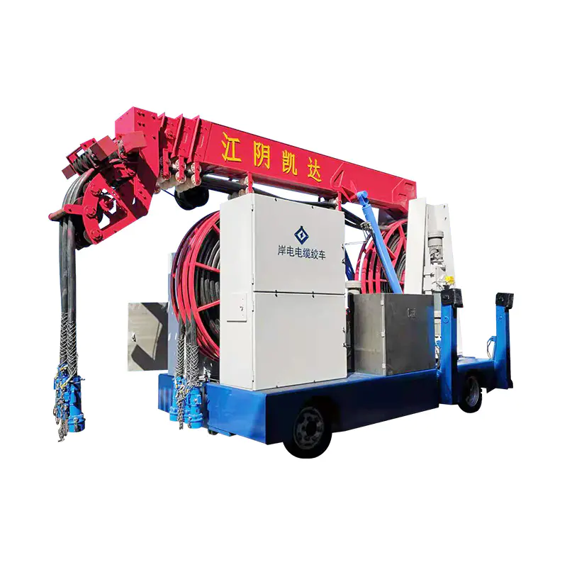
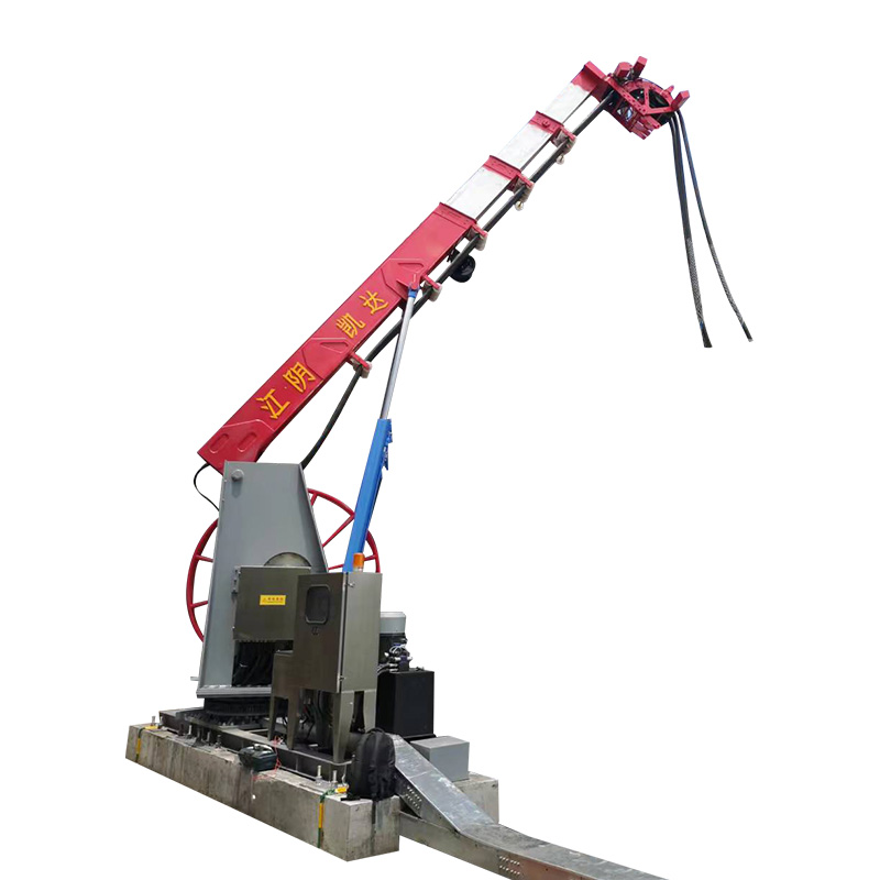
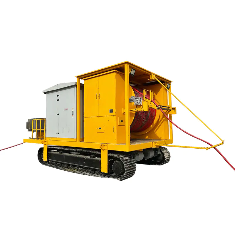
When the estimated tension approaches the cable's allowable limit, the safest decision is to stop pulling by hand and use a machine. A cable pulling winch provides controlled, constant tension and reduces the risk of snatching or over-stressing the conductor. For a single installation pull on a defined route, that is the equipment that matches the job.
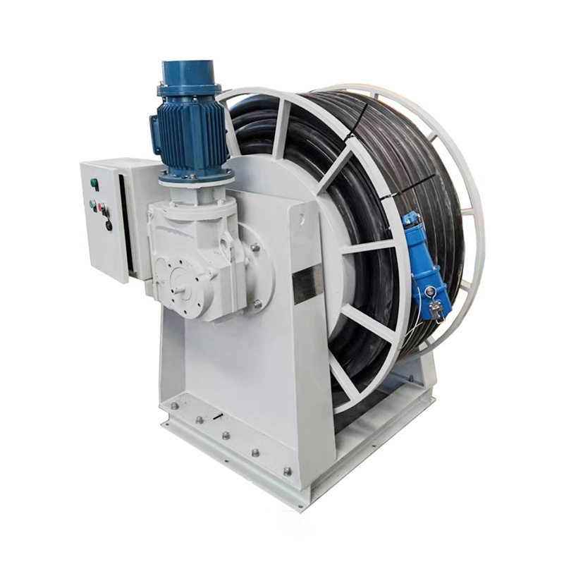 Marine Cable Pulling Winch for Controlled TensionThis winch provides steady, machine-assisted pulling when manual effort is unsafe near the cable's tension limit. It suits single installation pulls on defined routes, reducing snatch risk and over-stressing.View Product →
Before selecting a winch, compare the cable pull requirement to the winch's rated line pull, drum capacity, and speed control. Reviewing a guide to cable pulling winch types, specs, and selection can help you match the equipment to your project instead of over-specifying or underestimating the pull.
One-Time Pulling vs Continuous Reeling
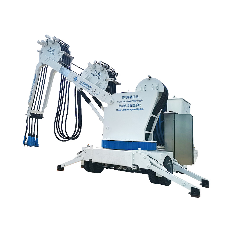
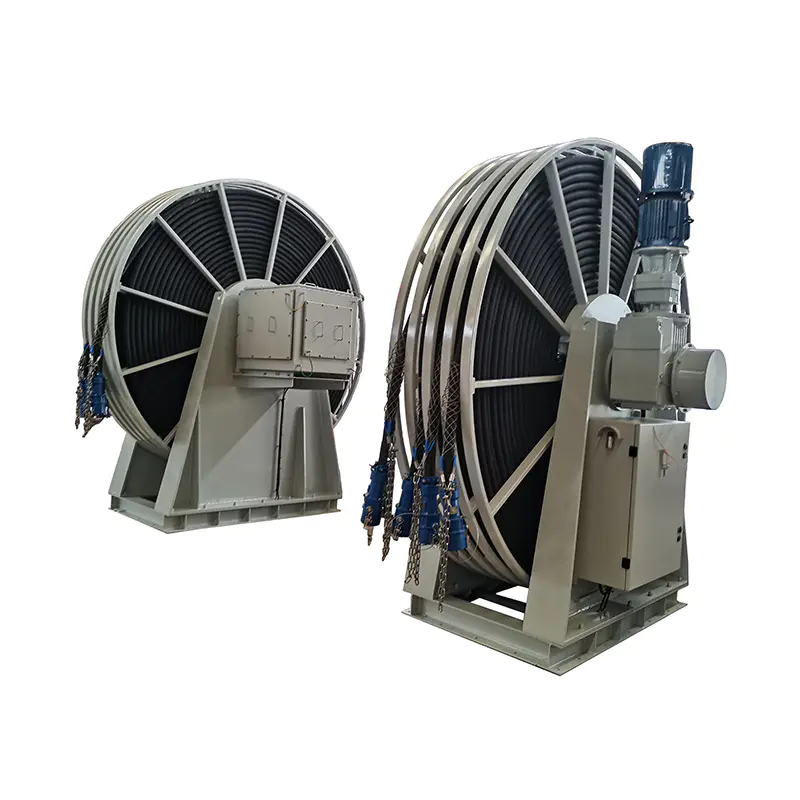
Cable pulling is not always a one-time installation event. In many industrial applications, the cable must be paid out and rewound as equipment moves: shore power supply cables for ships, tail cables on electric shovels, and power feeds for cranes are typical examples. A motor-driven cable reel is designed for that repetitive pay-out and take-up duty. It keeps tension consistent, prevents coil damage, and gives the operator a reliable way to control cable length.
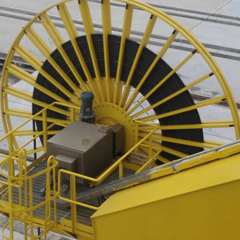 Motor-Driven Cable Reel for Repeated Pay-Out and Take-UpDesigned for repetitive cable winding in moving equipment like shore power supplies or shovel tail cables, this reel maintains consistent tension and prevents coil damage, with adjustable speed and direction.View Product →
Understanding the difference matters because the calculation that works for one-time pulling does not cover cyclic winding stresses. For repeated operation, the reel's speed, torque, and cable guidance all need to be evaluated as part of the machine selection.
Calculator Limitations and When to Bring in an Engineer
For short runs with clear access, a simple calculator gives enough confidence to proceed. For long routes, multiple bends, vertical sections, or medium- and high-voltage cables, a generic online calculator is not a substitute for a full route analysis. Professional pulling calculations account for the exact bend geometry, conduit fill, lubricant type, and cable construction, and they follow the installation method in the manufacturer's specification.
If your project falls into that category, consult a cable handling equipment manufacturer early. The drum configuration, motor drive, and braking system are as important as the winch's maximum pull force.
A cable pulling tension calculator is a planning tool, not a guarantee. Use realistic friction values, account for every bend, compare the result to the cable's actual limits, and bring in mechanical equipment when the numbers say so. That habit prevents the most expensive mistake in cable installation: discovering the pull is impossible halfway through.